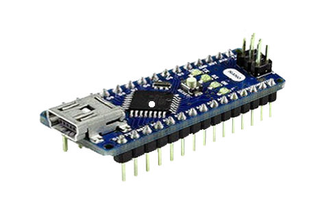
View of Arduino Nano showing mounting pins “headers.”
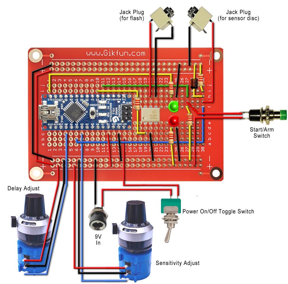
On this page is an image based step by step guide showing the basic assembly instructions for this Arduino Nano based adjustable flash trigger.
Please note colours of wires noted are irrelevant, they are quoted just to make instructions a little easier to follow.
Arduino Nano
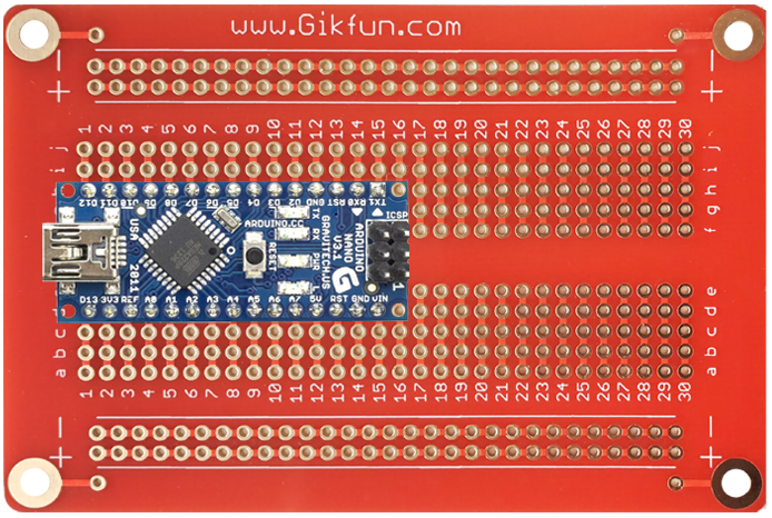
Mount Arduino Nano across center bar. Insert pins in nodes 1 to 15.
Don’t insert pins all the way, leave a gap underneath. Use a small piece of plastic to stop under side of Nano from touching the breadboard. Solder a couple of pins in corners and remove plastic spacer.
The Nano is now held in place while you solder the rest of the pins in place.
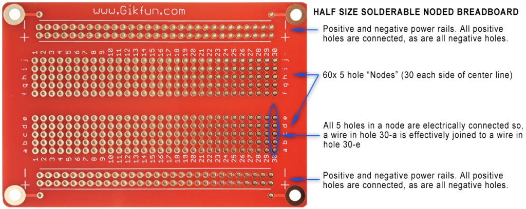
N.B. Soldering is done on the underside of the breadboard so use a piece of masking tape to hold components in place, so they don’t fall out when you turn board upside down.
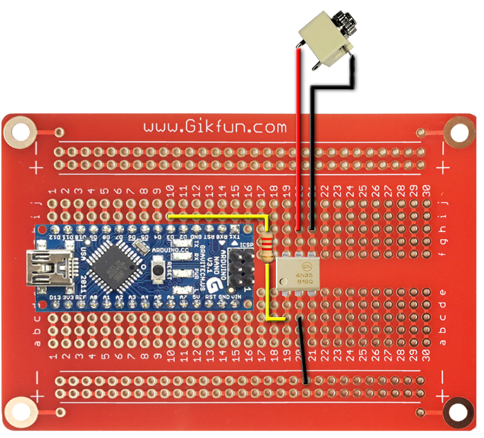
Optocoupler and flash port
Mount the 4N35 optocoupler across center bar into nodes 19 to 21.
NB…Observe the position of the dot in bottom left corner.
Black wire from lower node 20 to anywhere on lower negative power rail.
Mount a 220 Ohm resistor between lower node 19 and upper node 10 (connects to Nano pin D3)
* Ignore colours of bands on resistors shown in these images
* Use insulation stripped from other wires to insulate long leads on resistors.
Red wire from upper node 20 to positive tag on 2.5mm mono jack socket.
Black wire from upper node 21 to ground (negative) tag on 2.5mm mono jack socket.
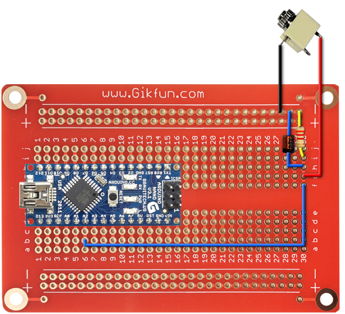
Zenner Diode and sensor port
Mount a1Meg Ohm resistor between upper node 30 and anywhere on upper negative power rail.
Mount 4.7volt Zener diode between upper node 30 and anywhere on upper negative power rail. NB…the cathode side of the diode must be connected to the node. The cathode end is signified by a distinctive line, usually black, at one end.
Red wire from upper node 30 to positive tag on 2.5mm mono jack socket.
Black wire from negative power rail to ground (negative) tag on 2.5mm mono jack socket.
Blue wire from upper node30 to lower node 6 (connects to Nano pin A2).

N/O (normally open) non-latching push button
Red wire from push button to anywhere on lower positive power rail.
Red wire form push button to upper node 27
Mount a 330 Kilo Ohm resistor between upper node 27 and anywhere on lower negative power rail.
Green wire from upper node 27 to upper node11 (connects to Nano pin D2)
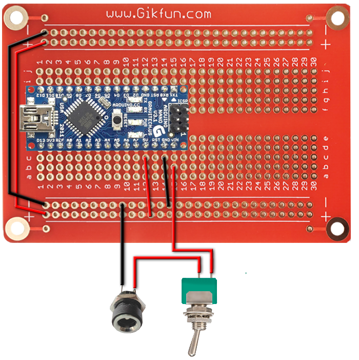
Power Supply
Black wire from ground tag on 5.5mm x 2.1mm DC power socket to anywhere on negative power rail
Red wire from positive tag on power socket to center pin on mini toggle switch
Reg wire from outside pin on toggle switch to lower node 15 (connects to Nano pin VIN)
Red wire from lower node 12 to positive rail (provides 5 volt supply to positive rails via Nano pin 5V)
Black wire from lower node 14 to negative power rail (connects Nano pin GND to negative rail)
Red wire from lower positive rail to upper positive rail
Black wire from lower negative rail to upper negative rail
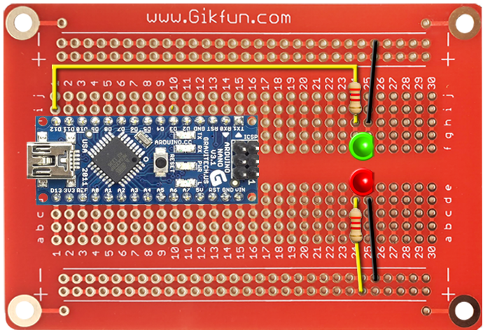
LEDs
Mount red LED across lower nodes 24 and 25. Long lead (anode +) to node 24, short lead/flat side (cathode -) to node 25.
Mount 470 Ohm resistor from lower node 24 to lower positive power rail
Black wire from lower node 25 to lower negative power rail
Mount green LED across upper nodes 24 and 25. Long lead (anode +) to node 24, short lead/flat side (cathode -) to node 25.
Mount 470 Ohm resistor from upper node 24 to upper node 1. Connects to Nano pin D12. (NB…wire will need soldered extension or join to additional wire length via unused node ie upper node 23)
Black wire from upper node 25 to upper negative power rail
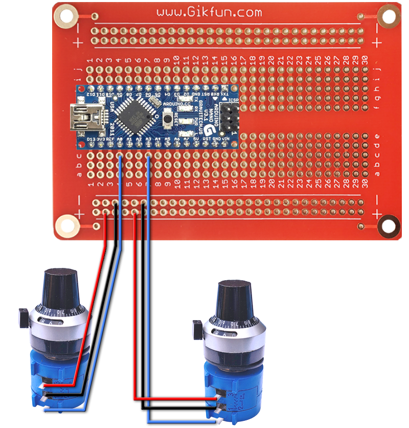
Potentiometers (delay and sensitivity adjustment)
Assumes use of 10 turn potentiometers as per see here
Red wires from both tag 3 on pots to lower positive power rails
Black wires from both tag 1 on pots to lower negative power rails
Blue wire from tag 2 (on delay pot) to lower node 4 (Nano pin A0)
Blue wire from tag 2 (on sens’ pot) to lower node 7 (Nano pin A3)
NB…tag 2 on these pots is the bottom terminal, on most other pots this is usually the middle tag of three.